5 Results
View results:
Sort by:

Structure Below Ground Level
Why does the integration/support of my building in the ground below the ground level not work?
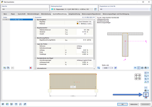
Graphic Templates for Printing Reinforcement Layout
How can I use graphic templates for multi printing of a reinforcement?
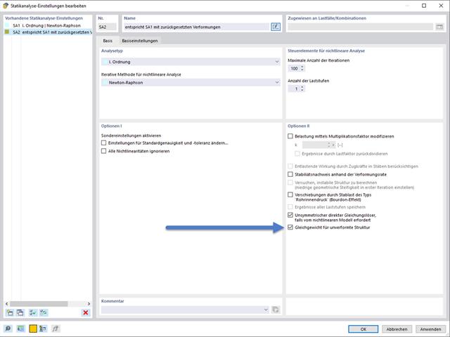
Setting Deformations to 0
How can I set the deformations from an LC/CO or a construction stage to 0?

